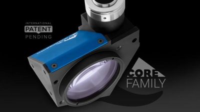
TC CORE series
Compact bi-telecentric lenses for sensors up to 2/3”

Key advantages
- Excellent optical performances
TC CORE bi-telecentric lenses deliver excellent optical performances as other comparable Opto Engineering® bi-telecentric lenses. - Extremely compact
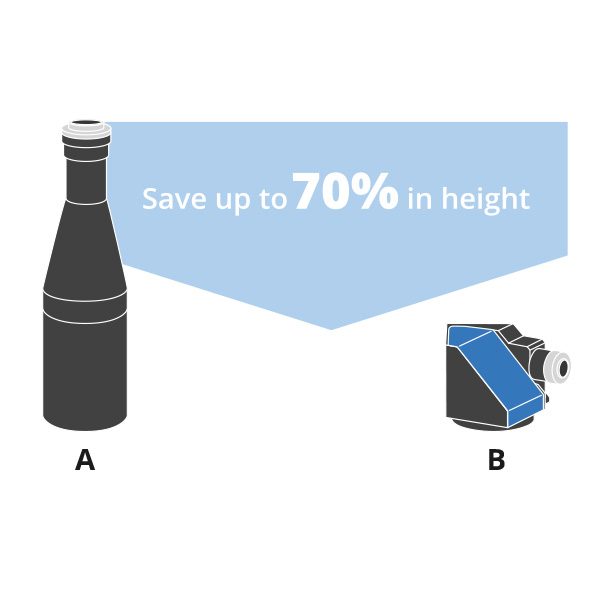
TC CORE lenses are up to 70% smaller than other telecentric lenses on the market. - Designed for flexibility and smart integration
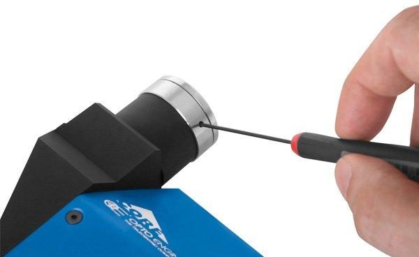
TC CORE lenses integrate a camera phase adjustment and can be mounted on multiple sides with or without clamps, allowing you to cut the costs. - Save you money
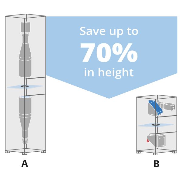
Systems integrating TC CORE lenses take much less space,resulting in lower manufacturing, shipping and storage costs. - Boost your sales
A smaller vision system or measurement machine is the solution preferred by the industry.
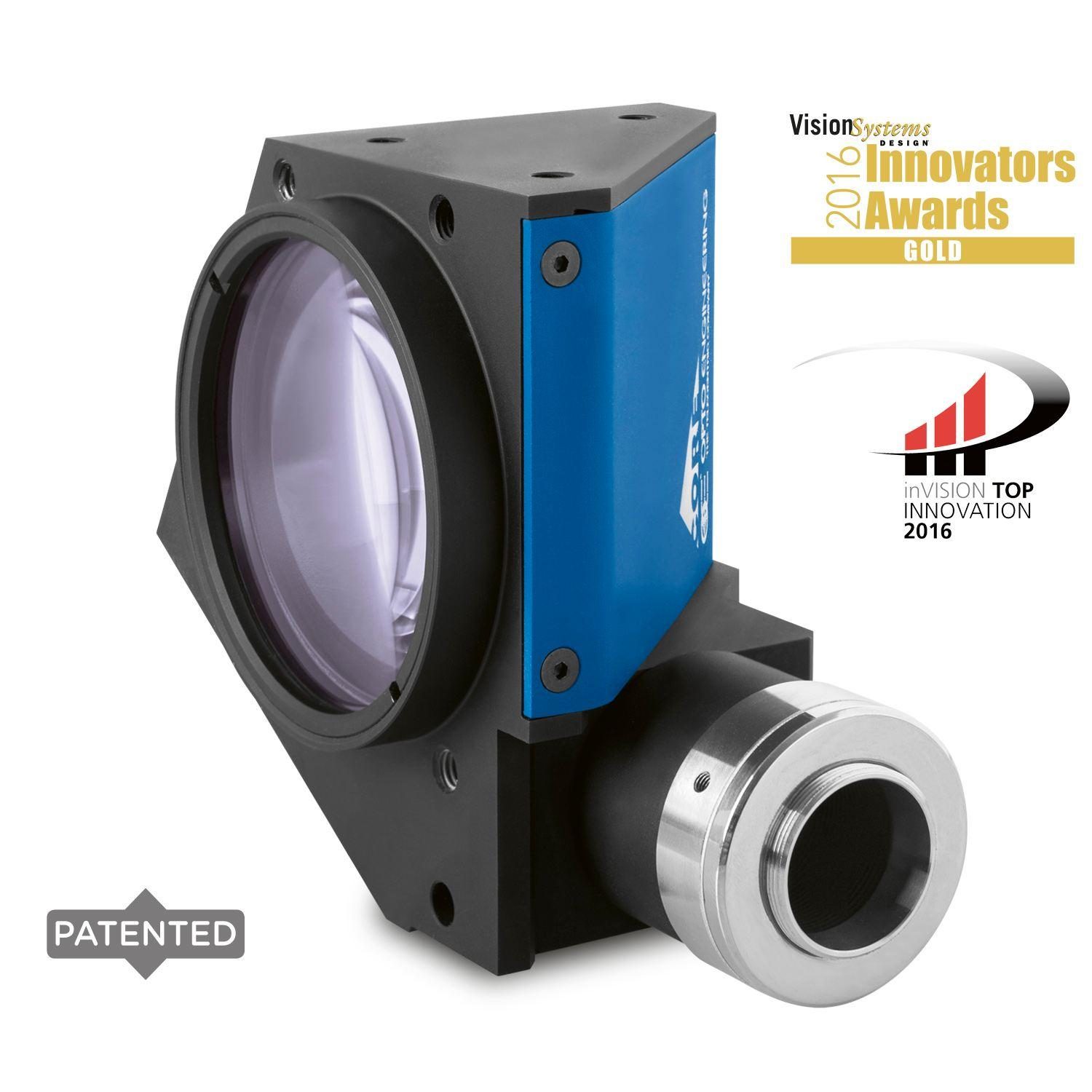
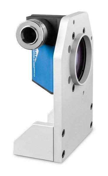
TC CORE bi-telecentric lenses for sensors up to 2/3” feature a truly revolutionary ultra compact opto-mechanical design.
These lenses deliver high-end optical performances and at the same time are up to 70% smaller than other double-sided telecentric lenses on the market, thus allowing to significantly downsize a vision system.
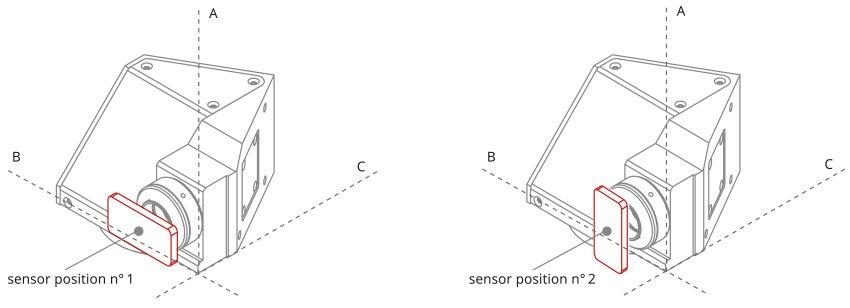
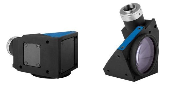
The unique shape has been expressly developed for maximum mounting flexibility.
TC CORE lenses can be mounted in different directions using any of the 4 sides even without clamps, allowing you to cut the system’s cost, and can be easily fitted or retrofitted even into very compact machines.
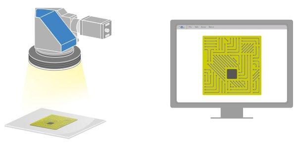
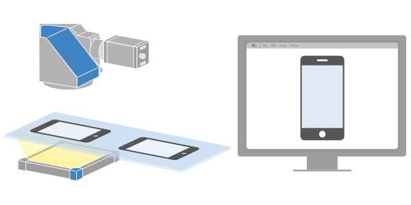
TC CORE bi-telecentric lenses can also be coupled with the new ultra compact LTCLHP CORE series telecentric illuminators to build super small yet extremely accurate measurement systems.
Advantages
Cost reduction
- Lower manufacturing cost due to less material employed
- Less space required for storage and use
- Lower shipment expenses due to smaller size
- Lower transportation risks
Sell more
- A smaller vision system or measurement machine is preferred by the industry

Notes
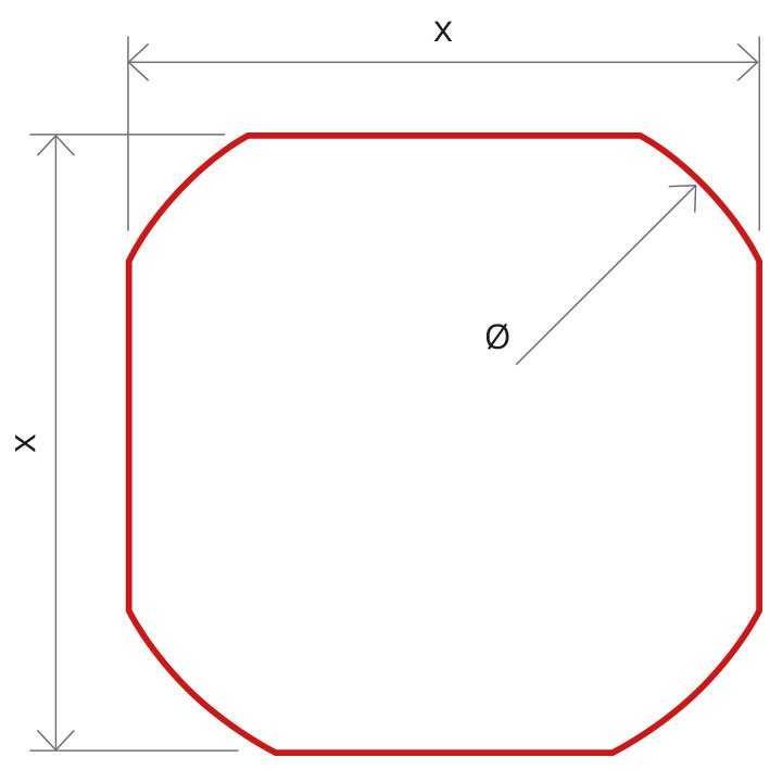
- Indicates the dimensions and shape of image, where "Ø =" stands for diameter and "x=" indicates the nominal image height and width (Tech Info for related drawing).
- Object field of view (mm x mm). For the fields with the indication "Ø =", the image of a circular object of such diameter is fully inscribed into the sensor.
- Working distance: distance between the front end of the mechanics and the object. Set this distance within ±3% of the nominal value for maximum resolution and minimum distortion.
- Working f-number (wf/N): the real f-number of a lens in operating conditions.
- Maximum angle between chief rays and optical axis on the object side. Typical (average production) values and maximum (guaranteed) values are listed.
- Percent deviation of the real image compared to an ideal, undistorted image. Typical (average production) values and maximum (guaranteed) values are listed.
- At the borders of the field depth the image can be still used for measurement but, to get a very sharp image, only half of the nominal field depth should be considered. Pixel size used for calculation is 3.45 μm.
- Object side, calculated with the Rayleigh criterion with λ= 520 nm
- Indicates the availability of an integrated camera phase adjustment feature.
- Due to the special shape of TCCR120xx it might be necessary to check the mechanical compatibility with your camera